Some examples of faults, damages and my repairs. Click the photos to enlarge. Enjoy!
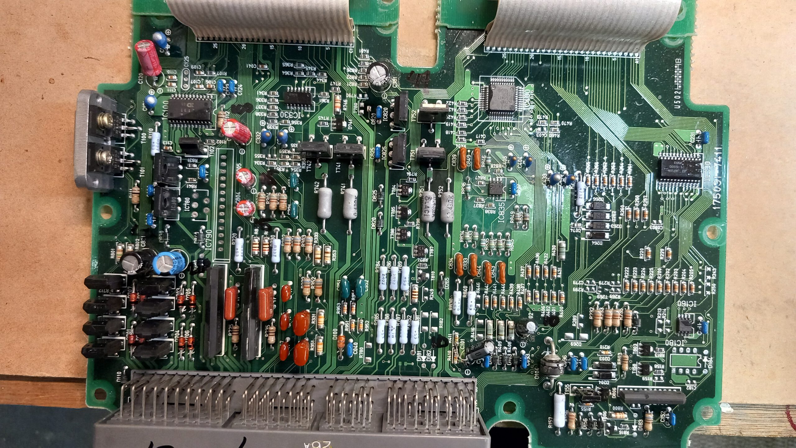
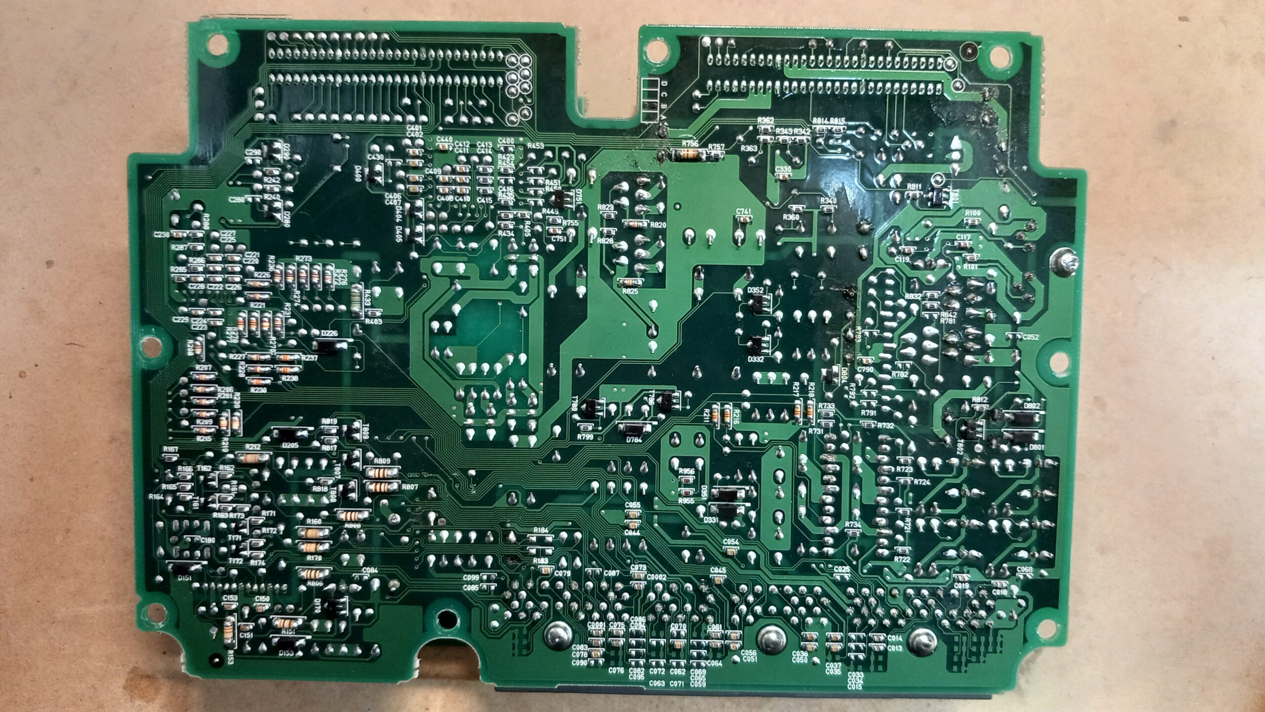
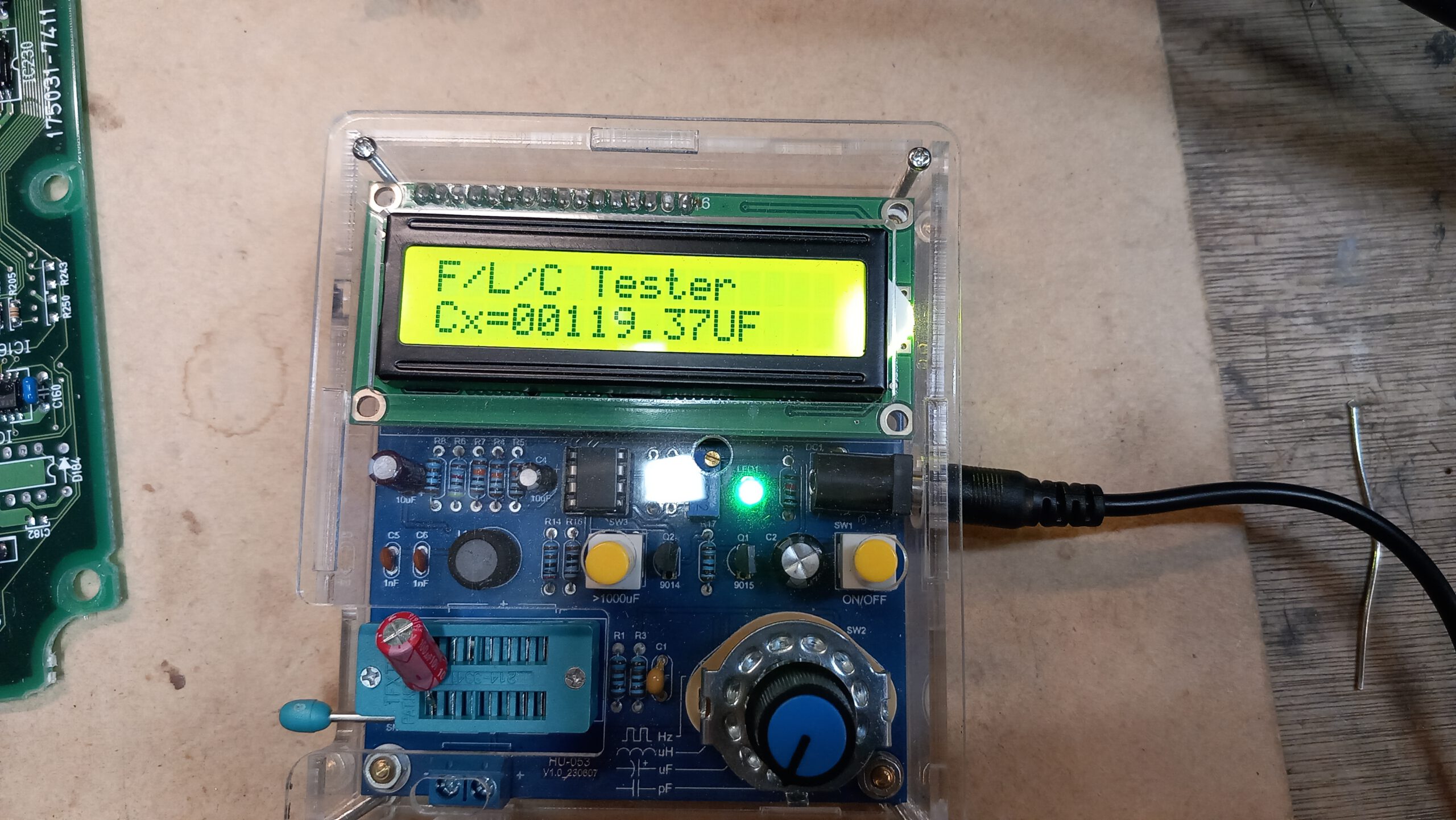
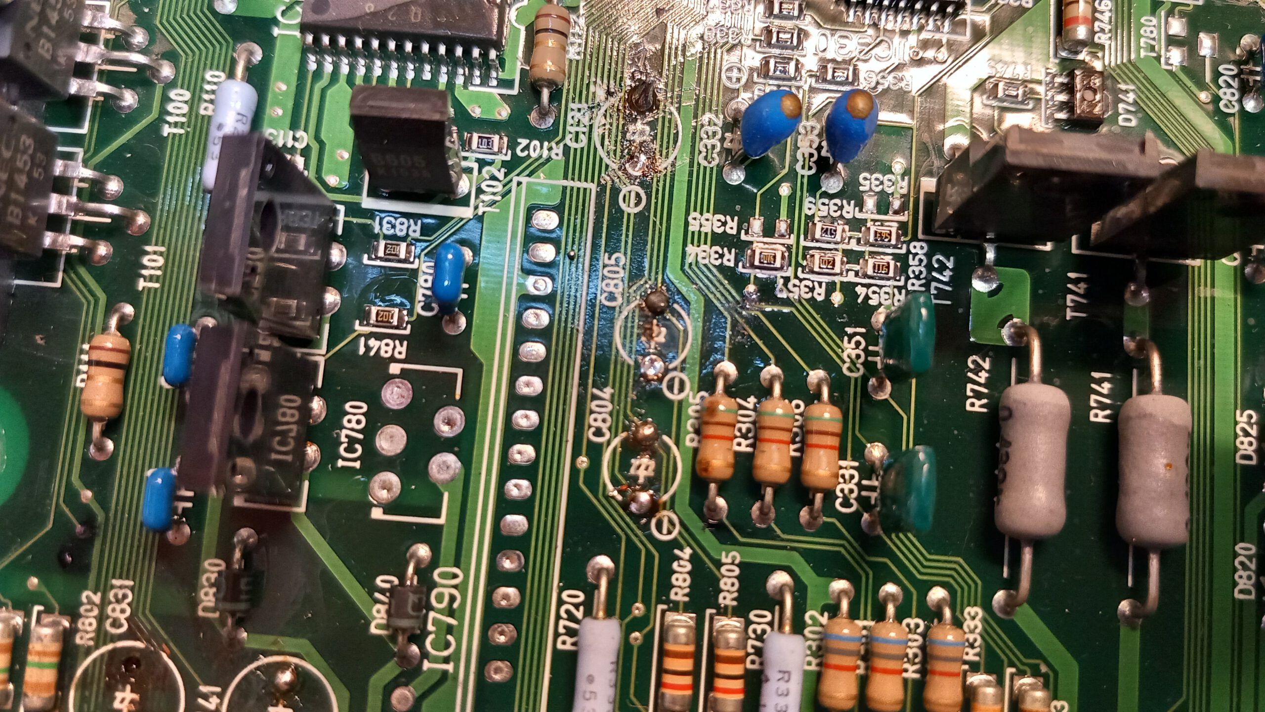
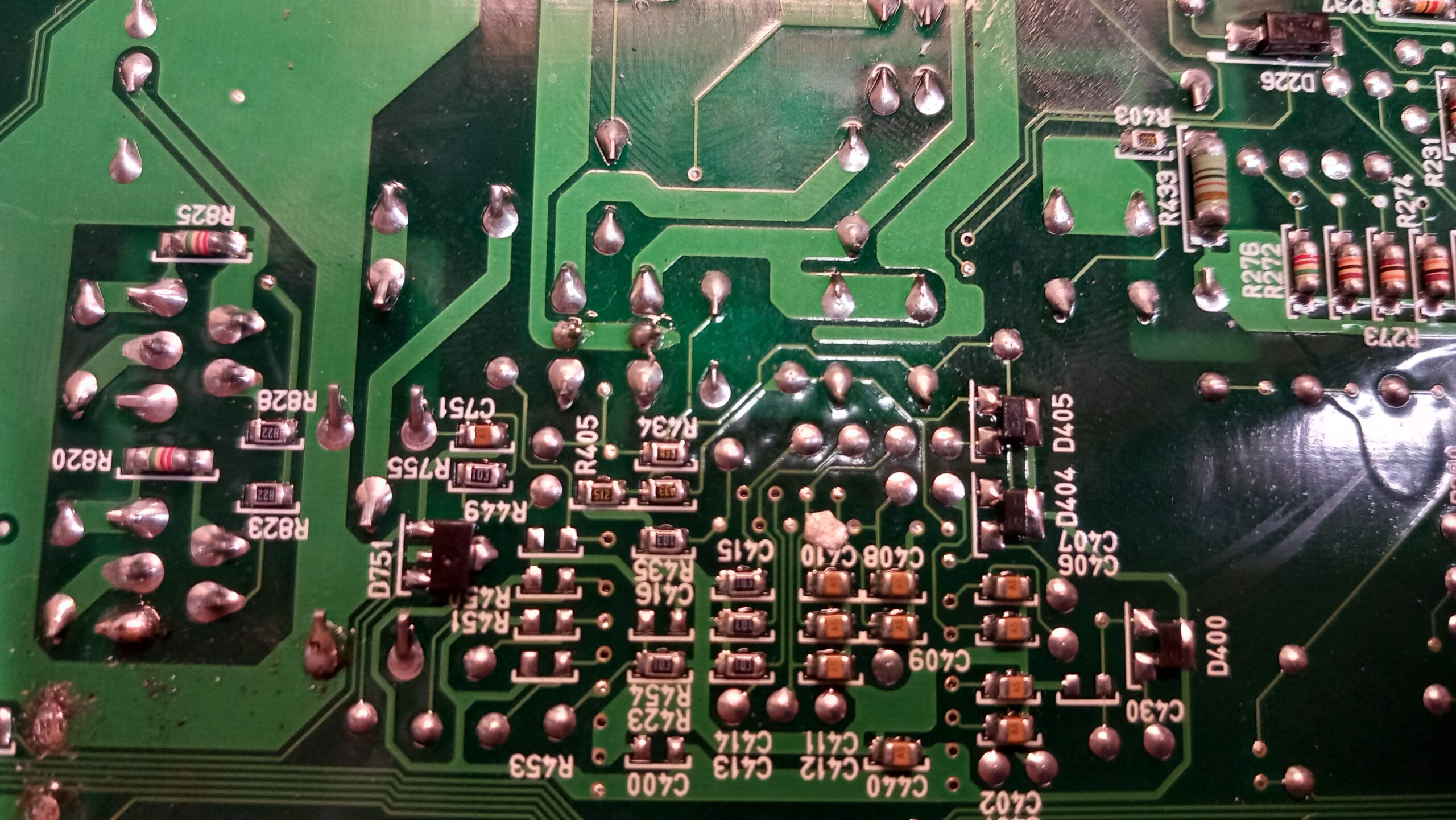
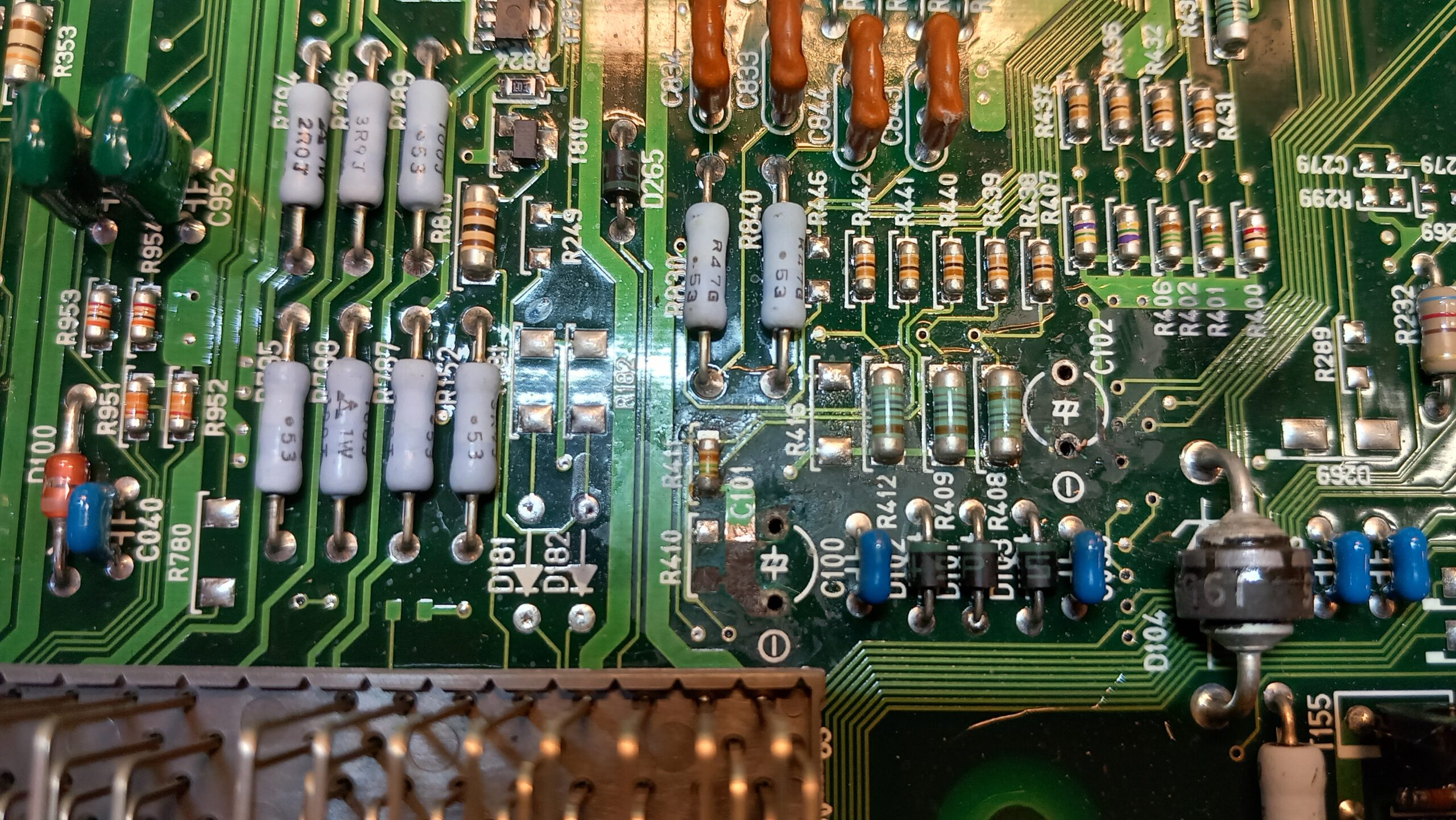
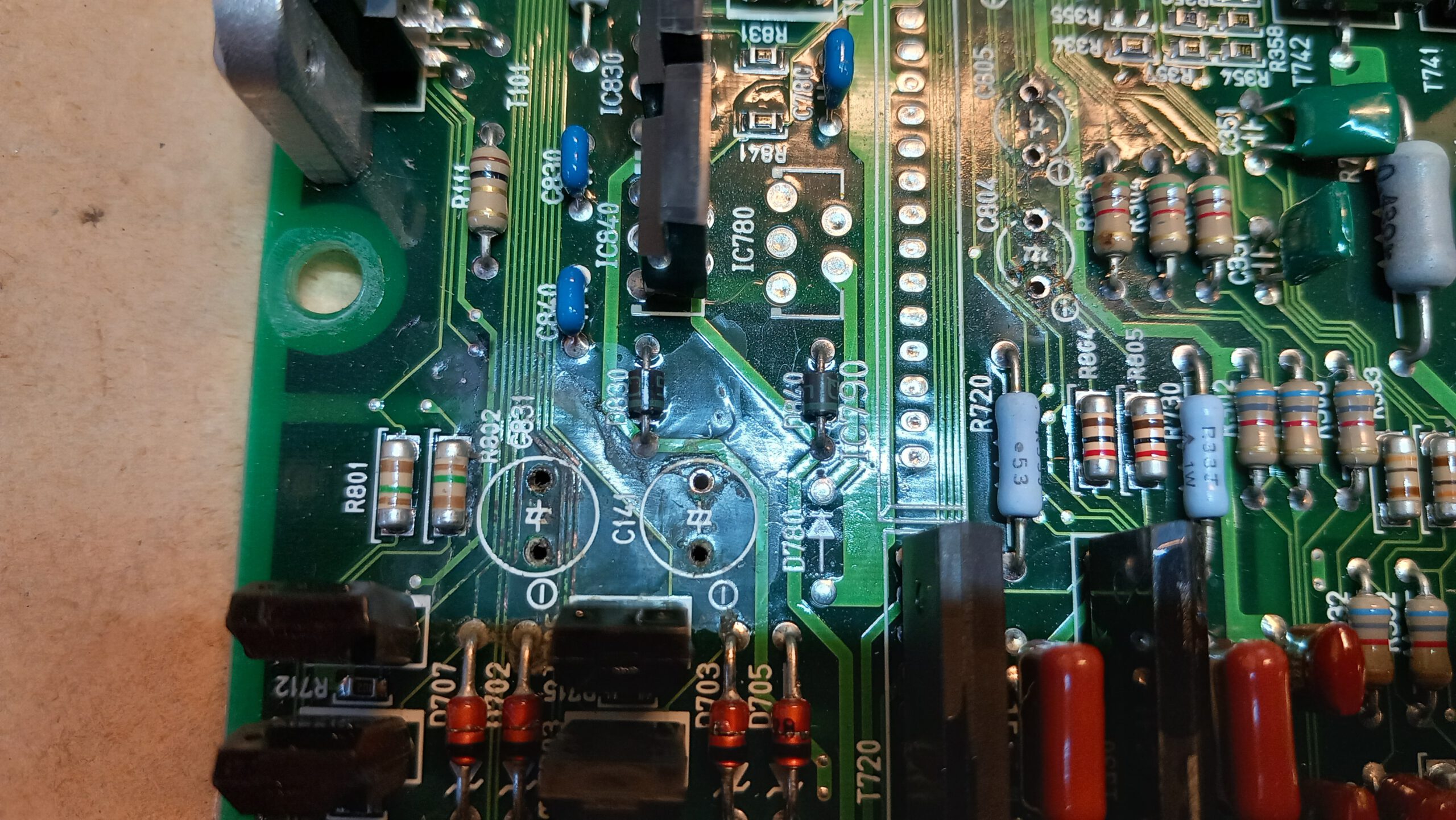
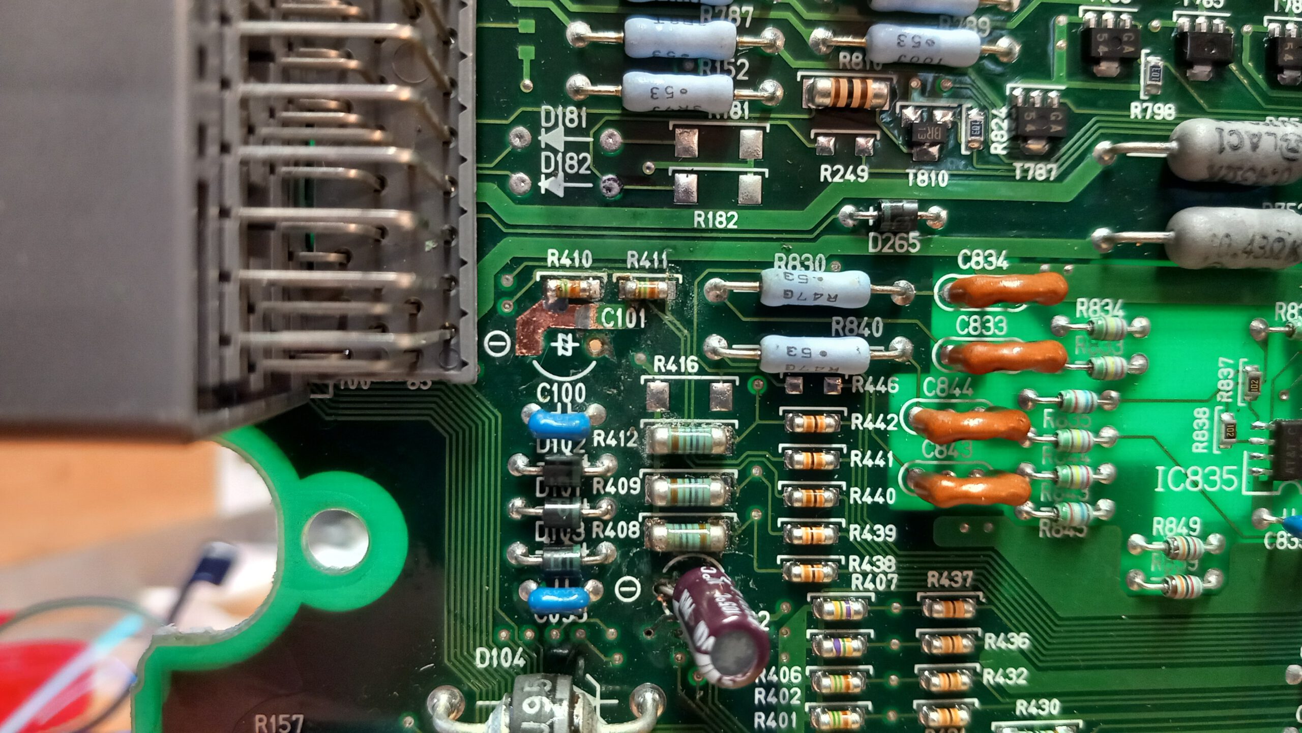
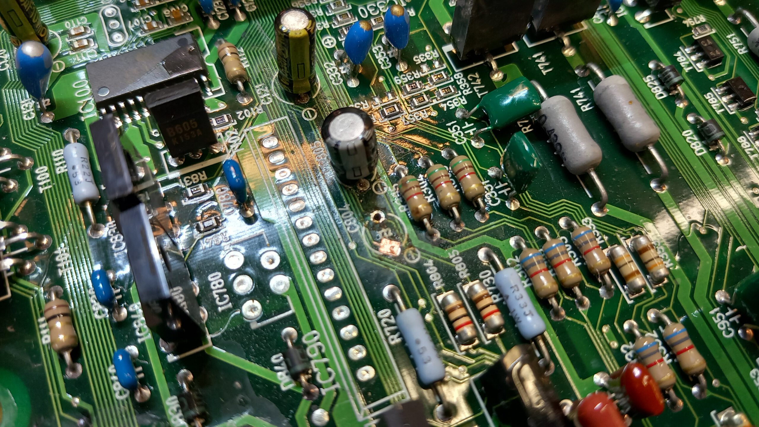
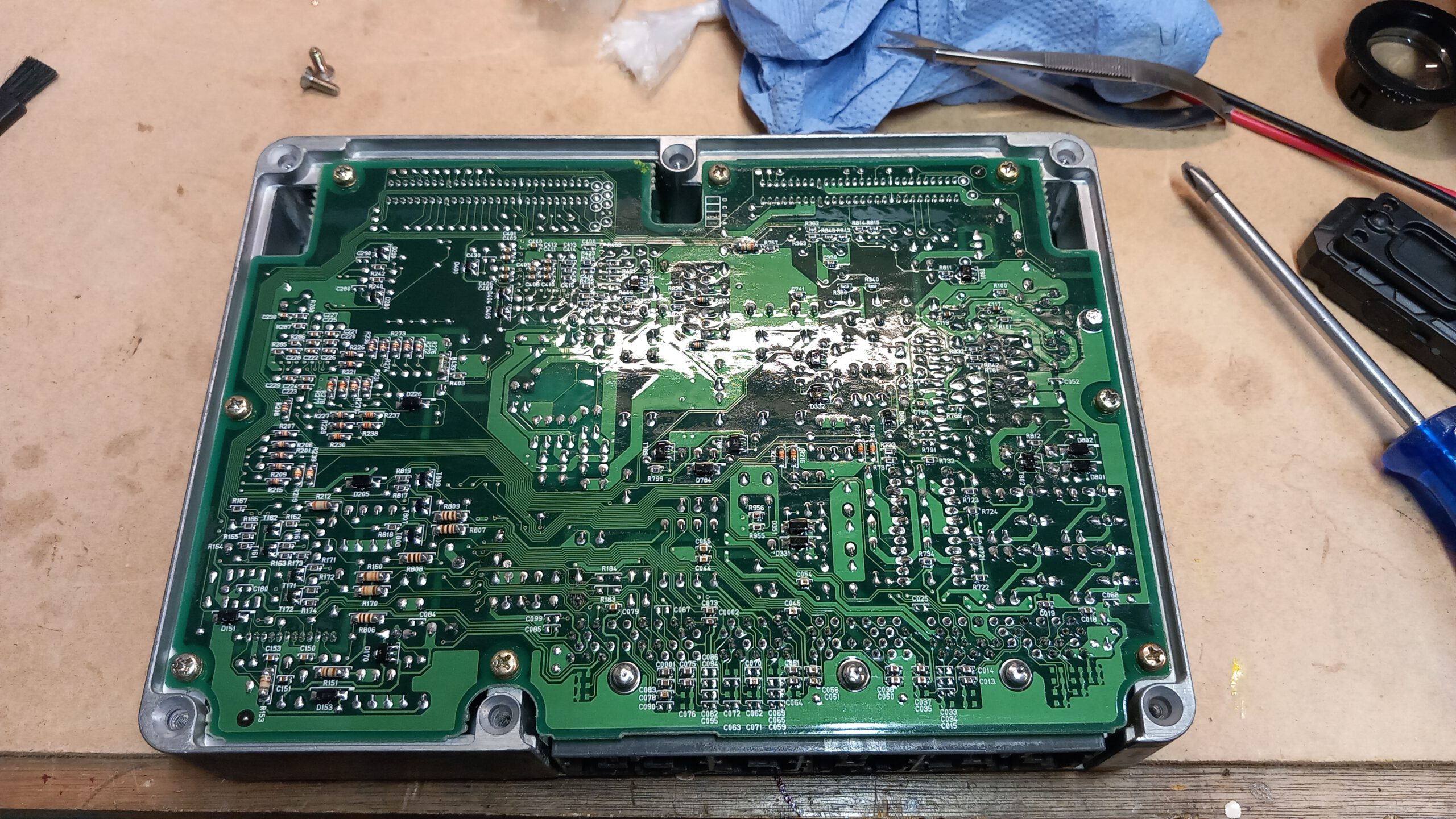
A UCF20 engine ECU came in. At first glance there doesn’t seem to be much wrong. But the capacitors have been replaced and something went terribly wrong.The lower side of the circuit board. Do you see the damage? I do!My homebuilt capacitor tester. Not only the capacitance counts, the ESR value is also critical in engine ECU’s.After desoldering the already replaced capacitors, the damage becomes visible. Traces and soldering pads are torn off, there is heat damage…Spilled blobs of solder created a short (at C410).A trace and resistor have been completely stripped at C101. The via of C102 has been pulled out.Pads and via’s are missing…A new trace has been created for C101. Position R410 has a new resistor soldered in.Trace repair at position C804. After applying soldering mask, the new capacitor can go in.Backside of the board after repairs. A fresh coat of conformal coating has been applied.
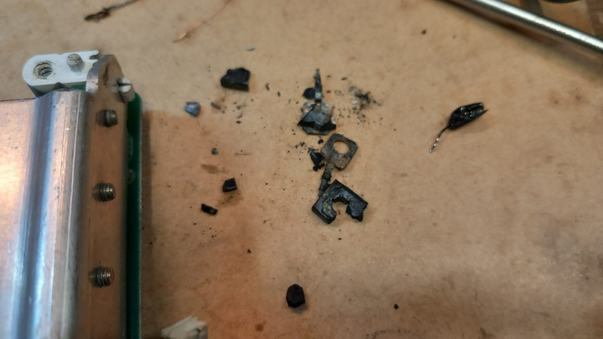
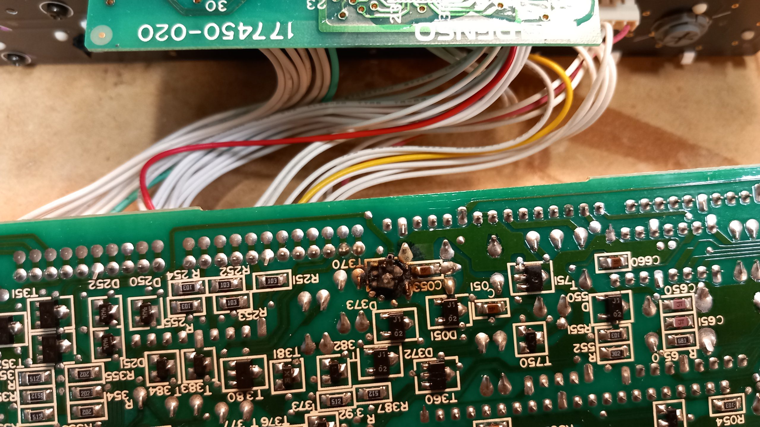
Here are some photo’s of a Toyota Celsior gauge cluster and climate control panel. The power board on the back of the gauge cluster blew up. Literally. These are the remains of some mosfets:
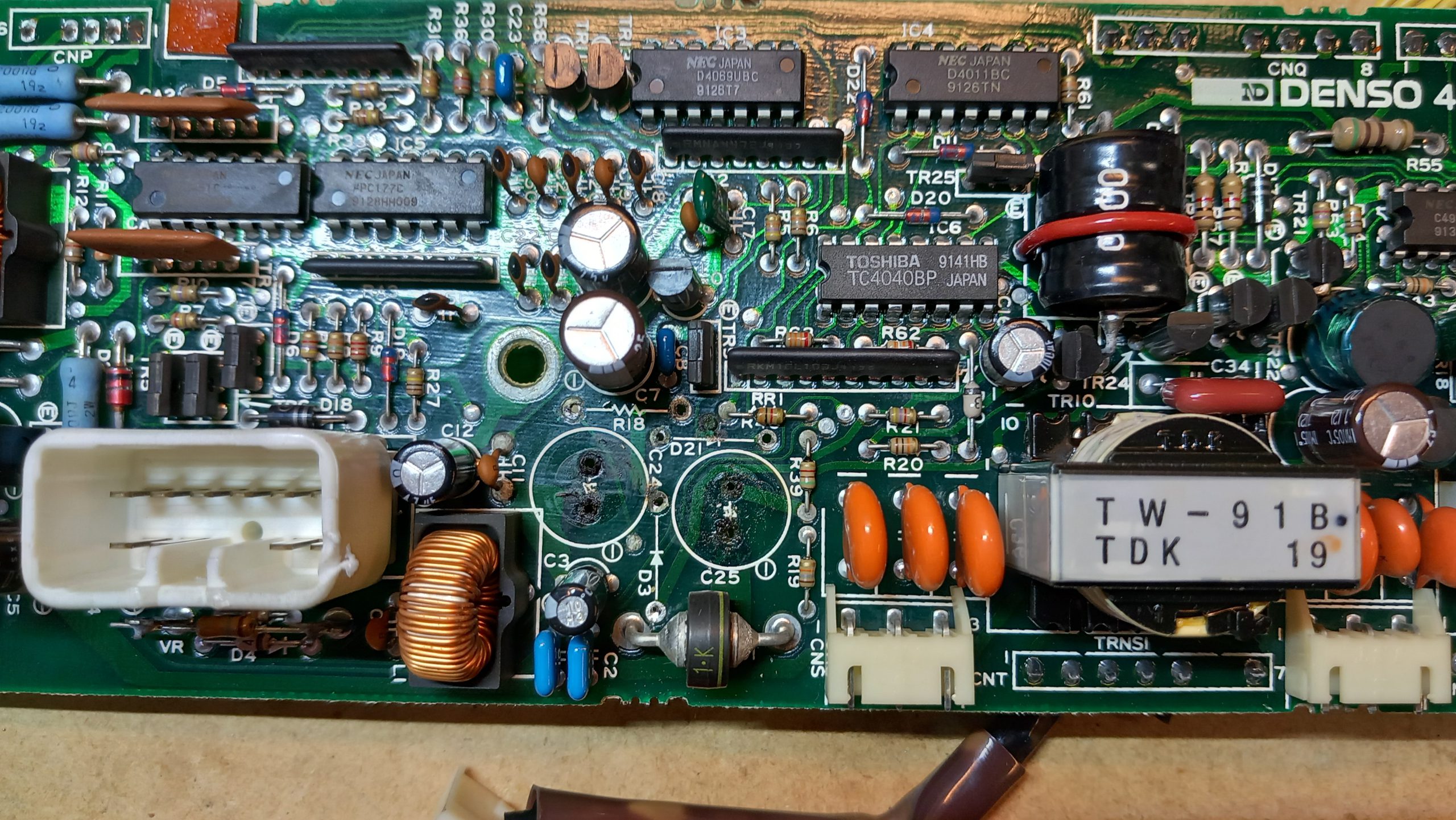
Two capacitors on the power board started leaking and damaged the traces underneath, including the vias:
The overload in the power board also affected the climate control circuit, as can be seen here:
The transistors were hard to identify, and a new soldering pad had to be created:
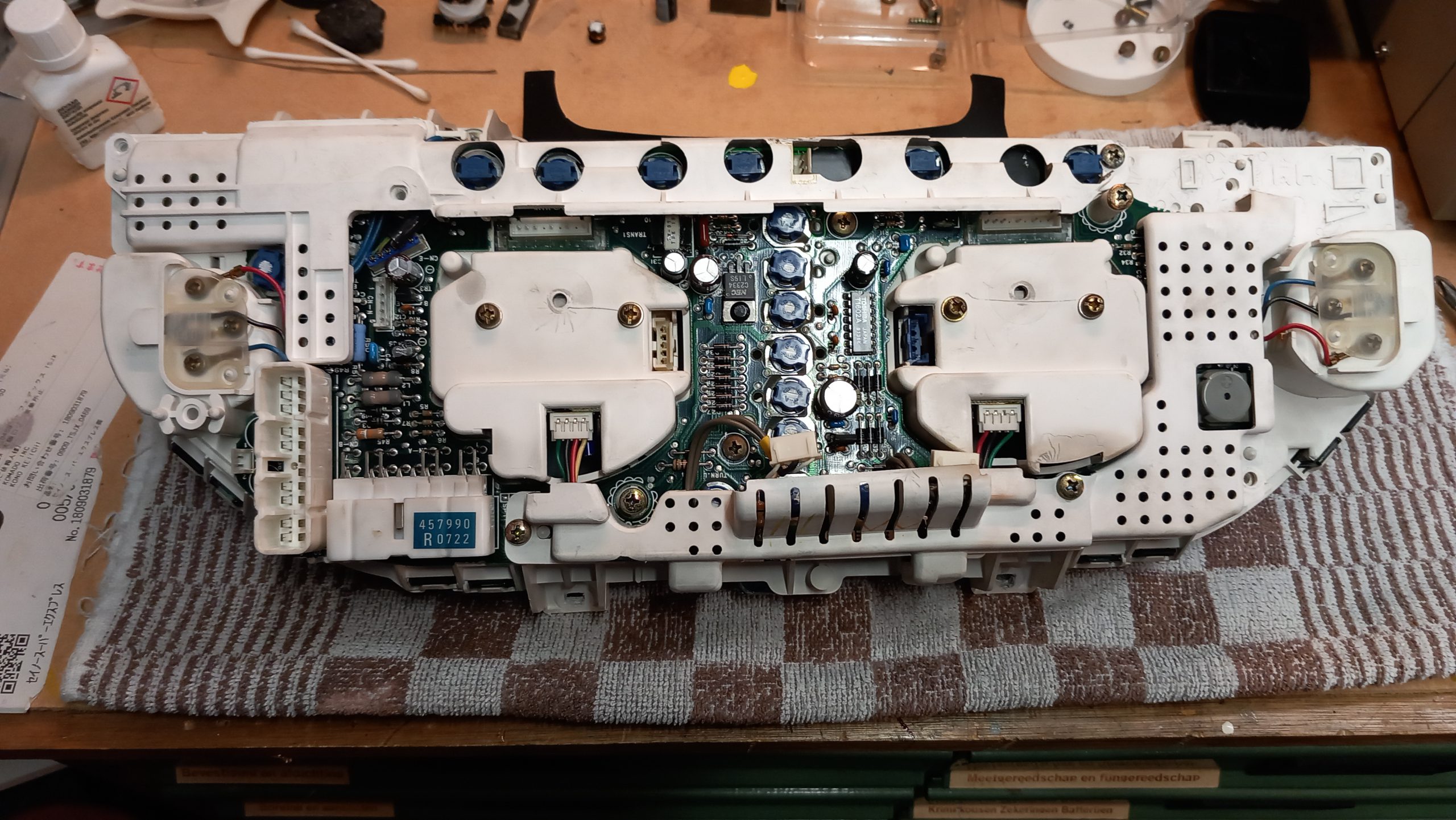
The instrument cluster was fully disassembled and cleaned:
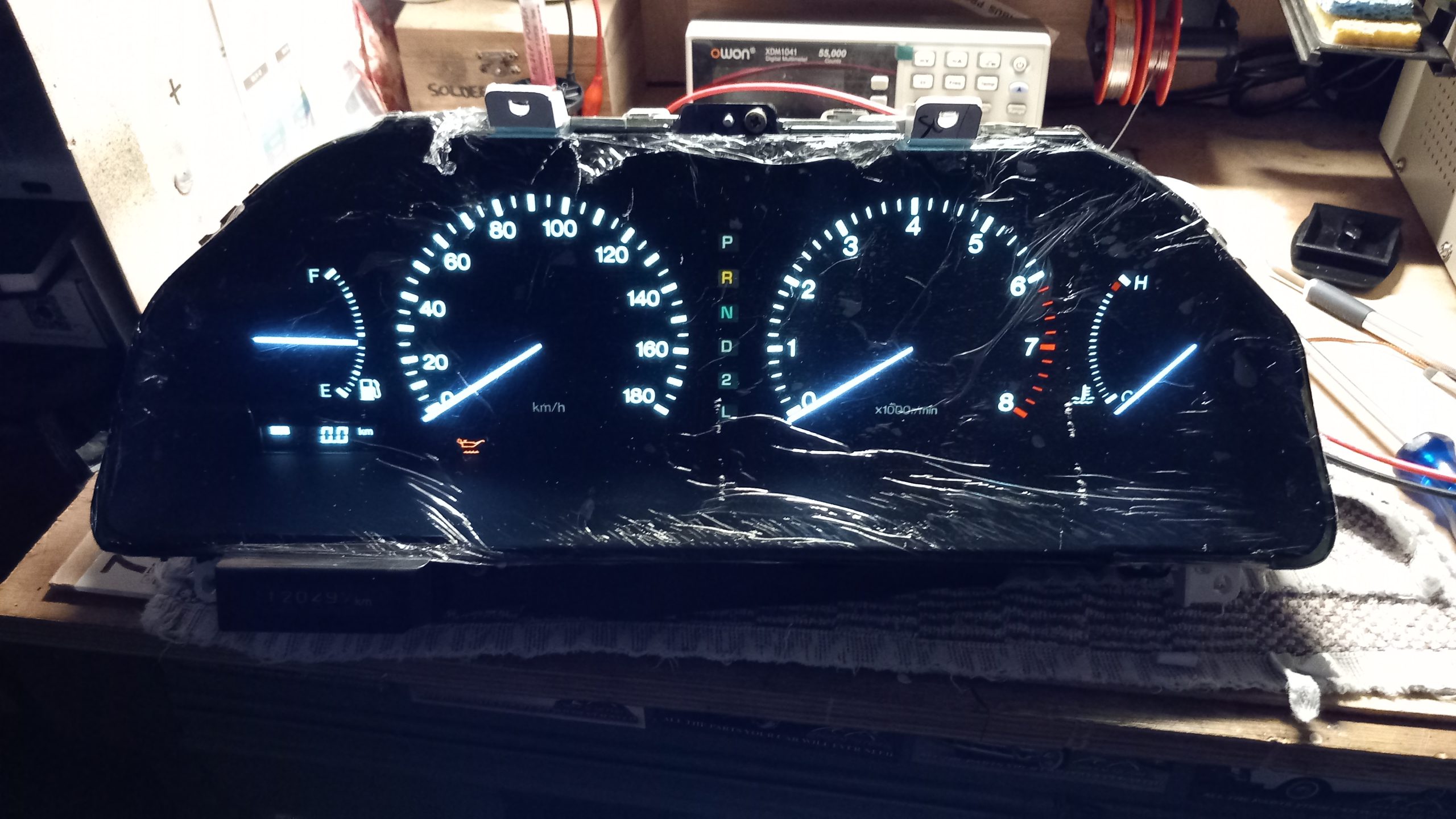
After two days of repairing traces, sourcing parts and damage repairs, the instrument panel was working again (there is a protective film on the lens to prevent scratching):